
Getting More From Archicad 3D Documents: From Documentation to Design Communication
Your Archicad model can do much more than produce plans, sections, elevations, and renderings. With 3D Documents, you can turn information already contained in your model into clear, flexible drawings that help communicate design intent, document details, and create compelling presentation graphics.
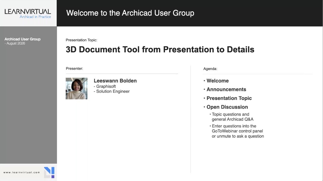
In a recent Archicad User Group session, Leeswann Bolden, Graphisoft Solution Engineer, explored how Archicad users can get more from 3D Documents and incorporate them into their everyday workflows.
The session went beyond simply introducing the tool. Leeswann demonstrated how cutaway planes, projection settings, model appearance, Graphic Overrides, associative dimensions and labels, and saved views can be combined to create everything from focused documentation views to presentation-ready diagrams.
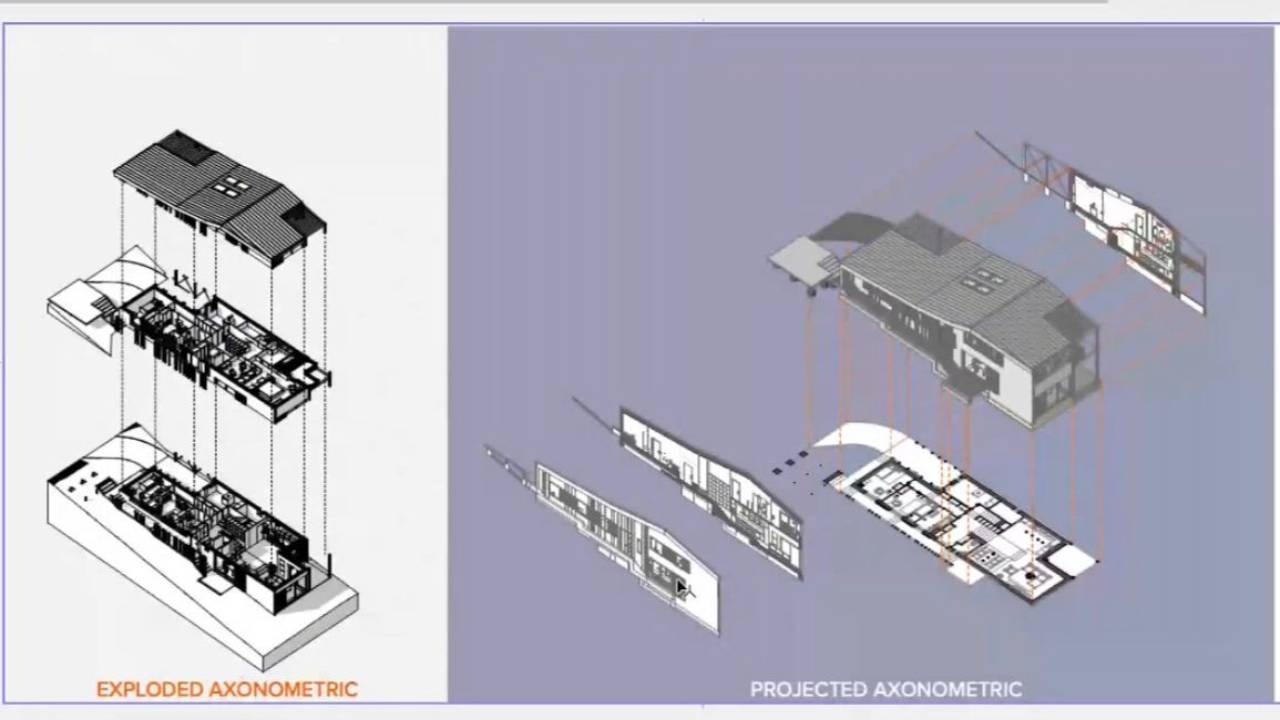
They also explored more advanced possibilities, including exploded axonometric drawings, projected axonometric views, custom graphic elements, and ways to use 3D Documents to communicate specific design information.
The goal? To help Archicad users think differently about the information already contained in their models—and how that information can be transformed into clearer documentation and more engaging visual communication.
And if you're not currently using 3D Documents as part of your workflow, this webinar may give you a few ideas worth trying.
What Makes 3D Documents So Useful?
One of the biggest advantages of 3D Documents is that they remain connected to the 3D model.
Rather than creating a static graphic and manually recreating information, you can generate a vectorial representation of your model that can be used for dimensioning, labeling, documentation, and diagrams.
That opens up a wide range of possibilities.
3D Documents can be used for:
- Site and floor plan graphics
- Interior and exterior views
- Construction documentation
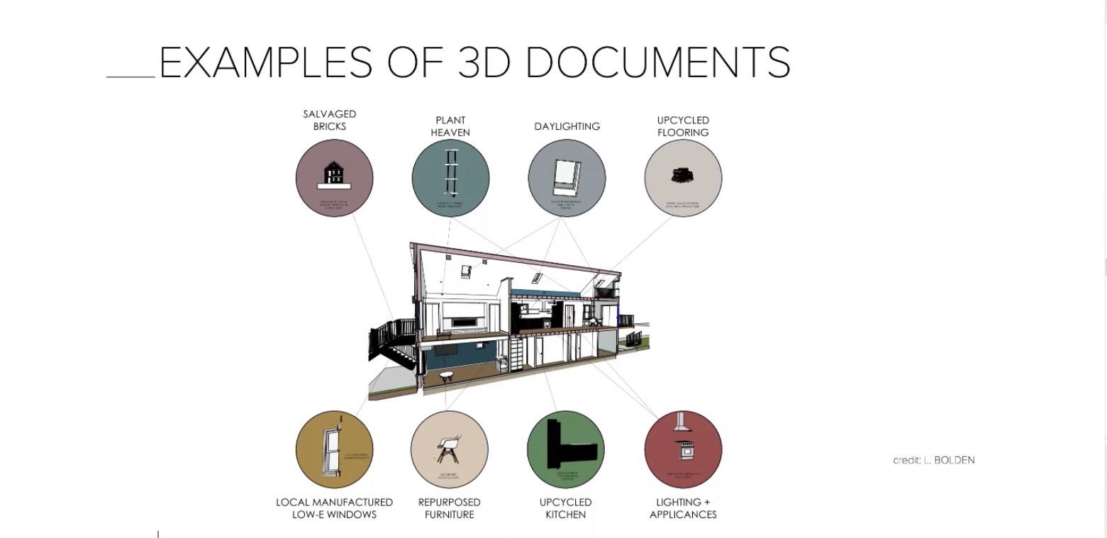
- Design diagrams
- Detailing and component studies
- Exploded axonometric drawings
- Presentation and marketing graphics
And because the drawings are generated from the model, changes to the underlying model can continue to inform the documentation.
Start With the View
Creating a 3D Document is surprisingly simple. From the 3D environment, you can create a new 3D Document from your current view.
But the real power comes from what you do before and after creating it.
The session walks through several of the settings that can dramatically change the way your final drawing looks, including:
Cameras, cutaway planes, model appearance, graphical overrides, and saved views.
Understanding how these pieces work together gives you much more control over the information you're communicating.
Cutaway Planes: Control What You See
One of the most useful tools demonstrated in the session was the 3D Cutaway Plane.
Cutaway planes allow you to trim the model to focus on the information you actually want to communicate. Unlike simply viewing the entire model, you can cut through a building to expose a room, isolate an interior condition, or create a more intentional diagram.
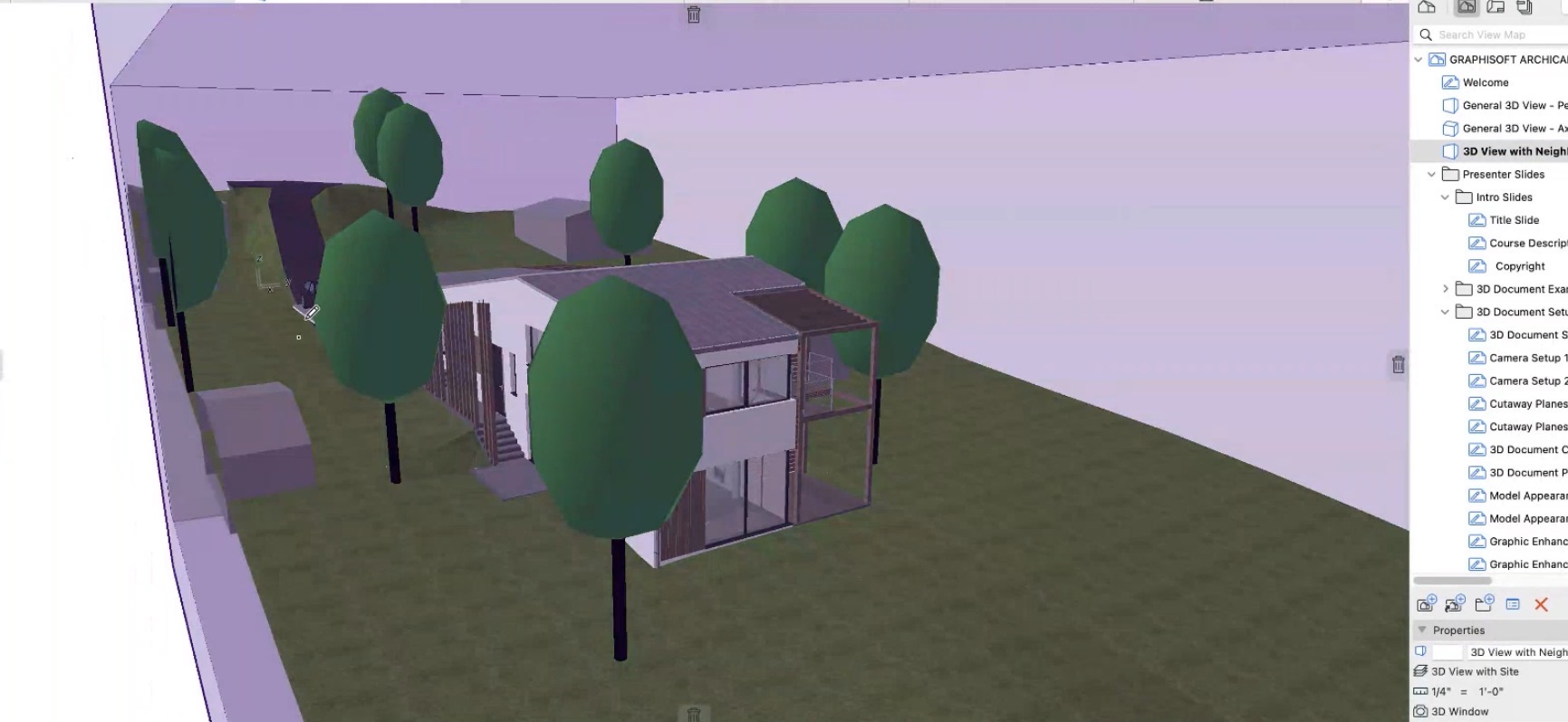
A particularly useful feature is that the cutaway planes can be saved with your views, allowing you to return to specific model cuts without recreating them from scratch.
And there's room to get creative: the presenter demonstrated that up to nine cutting planes can be used at one time.
That makes them especially useful for projects where you need to communicate complicated spatial relationships.
Want to see how those cutting planes are actually positioned and controlled? The session includes a live demonstration that is much easier to follow than a written explanation.
From Perspective Views to Axonometric Drawings
The way you project your model can completely change the information a 3D Document communicates.
Leeswann explored the difference between perspective and parallel/axonometric projections, including how different projection settings can be used to create top views, isometric views, and other controlled graphic representations.
This becomes particularly useful when you're creating diagrams or documentation where maintaining a consistent, measurable representation of the model matters.
The webinar also demonstrates how to create projected axonometric views by working with parallel projection settings and adjusting the model axes.
Make Your Drawings More Graphic With Model Appearance
Once you've established the view, you can start controlling how the model actually appears.
The Model Appearance settings give you options for controlling things such as:
- Color and monochrome presentation
- Surface colors
- Cut elements
- Uncut elements
- Vectorial surface information
- Shade and shadow
- Surface fills
This means the same model can produce very different types of drawings depending on what you're trying to communicate.
For example, a technical drawing may benefit from a more restrained black-and-white appearance, while a presentation graphic could use color and shadows to make the drawing more visually engaging.
The session goes deeper into these settings and demonstrates how seemingly small adjustments can change the character of the final drawing.
Use Graphic Overrides to Tell the Story
Graphic Overrides can take 3D Documents even further.
Instead of showing everything in the same graphic language, you can use overrides to emphasize specific elements.
The webinar demonstrates examples such as highlighting structural components or visually reducing furniture so that the viewer's attention stays on the architectural elements being discussed.
This is particularly valuable when creating diagrams.
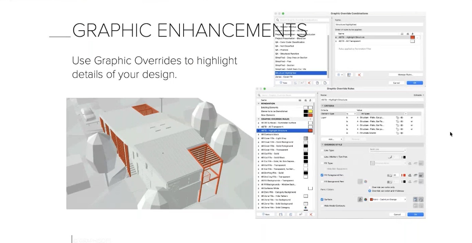
Rather than adding a large amount of 2D information after the fact, you can use the model and its graphic settings to create a drawing that communicates the idea more directly.
And these techniques aren't limited to construction documents. They can also be useful for design presentations, social media graphics, and other visual content where you want to quickly draw attention to a particular part of a project.
Don't Forget Dimensions and Labels
A common question during the User Group session was whether axonometric 3D Documents can be dimensioned differently from a typical floor plan.
The answer: the dimensioning workflow remains associative.
Because the 3D Document remains connected to the model, dimensions can be associated with model elements just as they are elsewhere in Archicad. The key is making sure you're associating the dimension with the correct element—especially when multiple elements overlap.
The same principle applies to associative labels, which can pull information directly from the selected model elements.
That can make 3D Documents much more than presentation drawings—they can become useful documentation tools.
Creating Exploded Axonometric Drawings
One of the more visually interesting topics covered was exploded axonometric drawings.
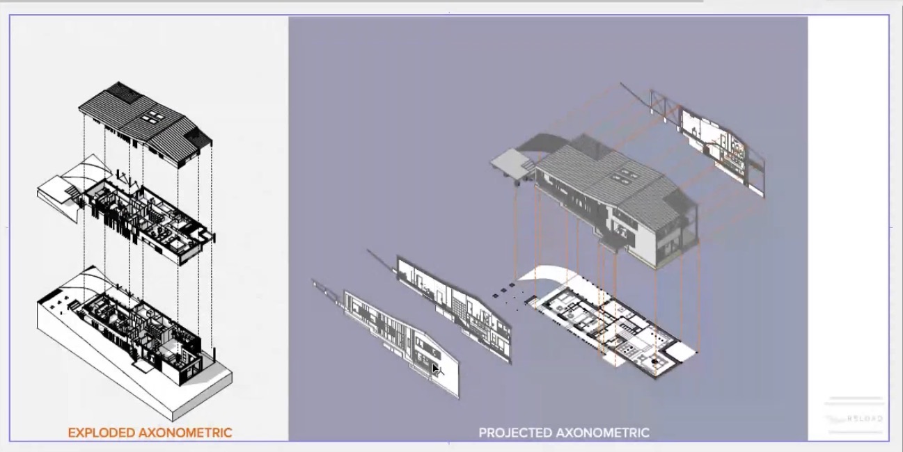
If you've ever created one manually, you know how time-consuming it can be.
The good news is that your 3D model provides much of the information needed to create these views.
However, the webinar makes an important distinction: there isn't simply an “explode model” button. The demonstrated workflow uses multiple views and cutaway planes to establish the different levels, with lines added manually to complete the graphic.
That distinction is important because it gives you a realistic understanding of what Archicad is doing automatically—and where some manual graphic work is still required.
There Are a Few Limitations
As useful as 3D Documents are, they're not without limitations.
The session also covered some of the things users should be aware of, including limitations involving PNG-based objects and surface representation. Some elements may not display as expected in a 3D Document.
The presenter also shared a few practical workarounds, including using a saved 3D view and layering a rendering over the 3D Document when additional surface information is needed.
These are exactly the kinds of details that are difficult to appreciate from a list of features alone—which is why the live demonstration is worth watching.
Think Beyond the Whole Building
Perhaps the biggest takeaway from the session is that 3D Documents don't have to represent an entire building.
You can use cutaways, the marquee tool, selections, and layer combinations to focus on very specific information.
Want to show a kitchen? A bathroom? A piece of casework? A structural system? A particular component?
The workflow can be adapted to the story you're trying to tell.
The presenter also encouraged users to think about using more detailed 3D information alongside traditional 2D documentation. Building more of the actual design into the model can reduce ambiguity and give contractors and project teams more information to work with.
That is where 3D Documents can become especially powerful: they help connect the model you've already built with the way you communicate the design.
🎥 Watch the Full
This recap only scratches the surface. The full recording includes live demonstrations, real project workflows, and audience Q&A that bring these techniques to life.
To see demonstrations, examples, and full explanations, join the LearnVirtual User Group Plus Community or log in to your LearnVirtual account. User Group recordings are available to User Group Plus, Basic, and Premium LearnVirtual members.
If you would like to learn more we invite you to join Learnvirtual to access OnDemand lessons, In-Practice presentations and LIVE weekly lessons.
Stay connected with news and updates!
Join our mailing list to receive the latest news and updates from our team.
Don't worry, your information will not be shared.
We hate SPAM. We will never sell your information, for any reason.
